20+ Circuit Diagram Ammeter
The emf of the source connected to the galvanometer and the shunt is 30 V. Ammeter Circuit Diagram Or Ammeter Diagram.

Barton Model Flying Club View Topic Gates Cyclon 2v Batteries
Web Draw a diagram showing an ammeter correctly connected in a circuit.
. Ammeters vary in their operating principles and accuracies. Web Science Physics Physics questions and answers 20 In the circuit diagram shown below ammeter A1 reads 10. The device can measure both alternating current as well as direct current.
Web An ammeter circuit diagram is a vital document for understanding a particular electrical system. The circuit does not. In the circuit shown below the reading if the ammeter A is assuming all instruments are ideal.
Ammeter Internal Circuit Diagrams are a critical part of any electrical engineers toolkit. Describe how a galvanometer can be used as either a voltmeter or an ammeter. Web This device measures current by measuring voltage between two points in a circuit.
Web An ammeter is a device used to measure the amount of current in an electric circuit. Find the resistance that. Web In this explainer we will learn how to use ammeters in electric circuits to measure the current through a component in the circuit.
Web The most common way to measure current in a circuit is to break the circuit open and insert an ammeter in series in-line with the circuit so that all electrons flowing through. Web In circuit diagrams the symbol for an ammeter is a circle with a capital A inside. The ability to interpret and understand ammeters internal.
By understanding the components of an ammeter circuit. Recall that electric current is the flow of. Web The most common way to measure current in a circuit is to break the circuit open and insert an ammeter in series in-line with the circuit so that all electrons.
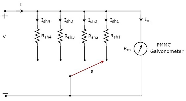
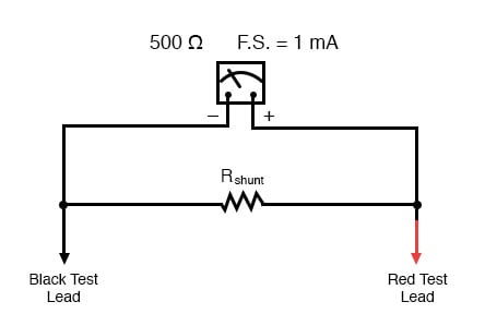
Web Weve been told that each one of these circuit diagrams A B C and D shows us a cell a bulb and an ammeter. S2 What is the reading of ammeter. Web The circuit diagram represents a galvanometer combined with a shunt resistor.
Lets recall that the circuit symbol of a cell looks like this. Web Solution Suggest Corrections 25 Similar questions Q. This is often done with multiple meters connected in series so that a single.
![]()
20 Pressure Calibration Illustrations Royalty Free Vector Graphics Clip Art Istock Metrology Pressure Gauge
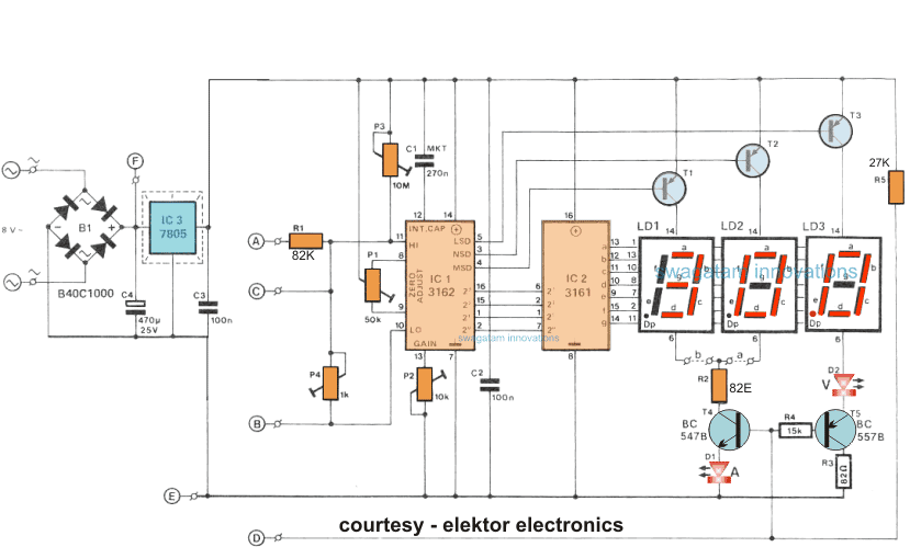
How To Make A Digital Voltmeter Ammeter Module Circuits Homemade Circuit Projects

Ac 80 260v 20a Lcd Digital Volt Watt Power Meter Ammeter Voltmeter 110v 220v Amazon Com Tools Home Improvement
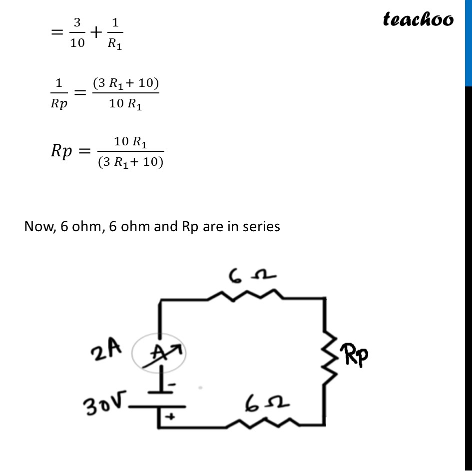
Term 2 Sqp In Above Circuit If Current Reading In Ammeter A Is 2a

What Is An Ammeter Symbol Circuit Diagram Types And Applications
Voltmeter And Ammeter Values On Schematic Circuitlab
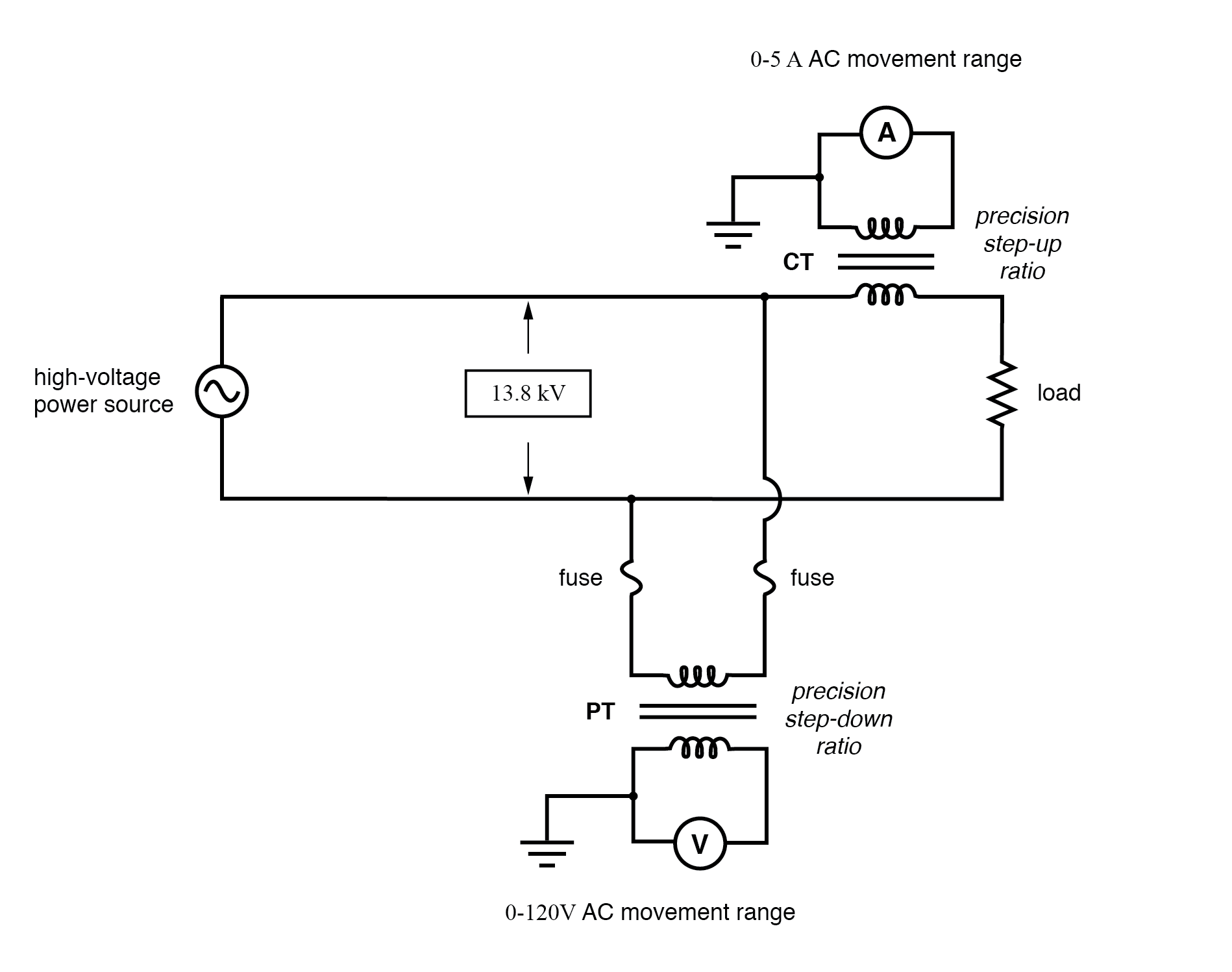
Ac Voltmeters And Ammeters Ac Metering Circuits Electronics Textbook
What Will Happen To An Ammeter Reading If More Resistors Are Added Quora
Help With Circuit Questions The Student Room
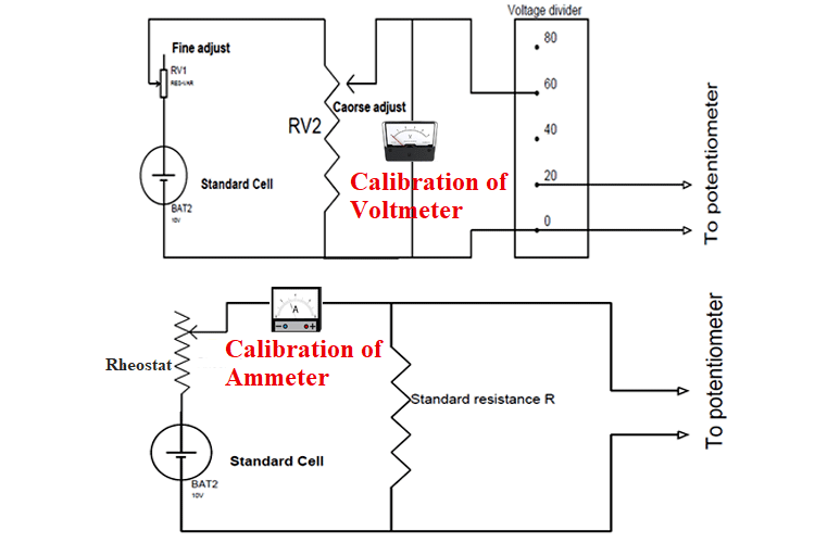
Calibration Of Ammeter Voltmeter And Wattmeter Using Potentiometer
Ammeter Design Dc Metering Circuits Electronics Textbook
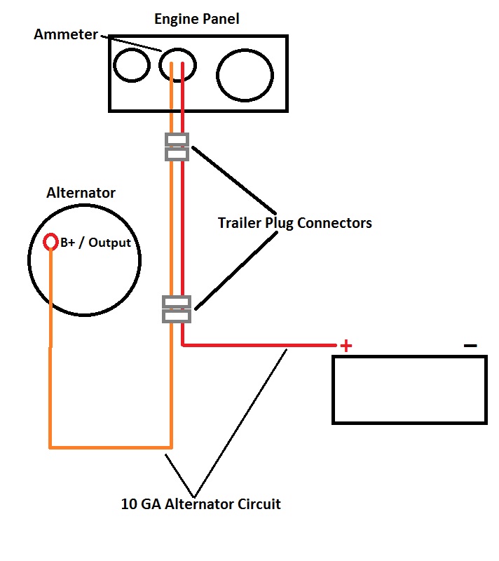
Universal Diesel Wiring Harness Upgrade Photo Gallery By Compass Marine How To At Pbase Com
Ammeter Working Principle Circuit Diagram Types And Applications
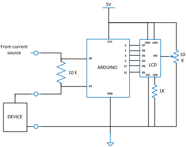
Diy Arduino Based Ammeter
What Are The Connections Needed When Measuring The Current Voltage And Resistance Of A Component Using An Ammeter Voltmeter And Ohmmeter Respectively Quora

Arduino Ammeter Circuit
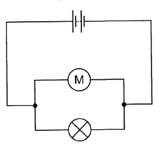
A Draw A Ammeter Symbol On This Circuit Diagram Where It Would Measure The Current Through The Electric Motor Teachernotes4u